Tuft testing - Fuelly Forums

Click here to see important news regarding the aCar App

Reply
 
Thread Tools Display Modes
 
Old 07-26-2006, 06:57 AM   #1
Registered Member
 
MetroMPG's Avatar
 
Join Date: Dec 2005
Posts: 4,223
Country: United States
Tuft testing

Quote:
Originally Posted by Mighty Mira
Could you go over the theory behind tuft testing and what exactly to look for?
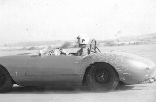
Tufts are wool/yarn/ribbon lengths taped on & around the area of the car you want to study.

In attached airflow, the tufts will stream back relatively smoothly, maybe the ends flicking slightly. In turbulence, tufts will swirl around more dramatically, sometimes in directions apparently at random depending on the severity of the turbulence.

Also in attached flow, the tufts will stream in the direction of airflow, often "pointing" towards low pressure areas, particularly near transitions (e.g. rear quarter / "C" pillar area on a 3-box vehicle).

Do a google image search and you'll find some examples like this:


... showing attached flow ahead of and above the wheel well, and turbulence after the wheel well. (Wheel skirts, anyone?)

If you've done any sailing, you're already familiar with applied tuft testing, since "telltales" on the sails are used to trim the sheets and/or change heading to maintain laminar flow on the sail for maximum lift.


. I've spent many hours looking at sail telltales. In this pic, the upper pair (one on each side) shows the top portion of the sail is properly trimmed, and the lower set shows separated flow on the outside of the sail (the outside telltale is pointing straight down), meaning it's stalled or overtrimmed.


Tuft testing a Lexus LS 400 - note separation at the forward end of the trunk/boot lid (tuft is lifted in turbulence) and reattached at the trailing edge (tufts streaming back).

Tuft testing helps you see airflow, while coastdown & road testing quantifies its effects.
__________________

MetroMPG is offline   Reply With Quote
Old 07-26-2006, 08:23 AM   #2
Moderator
 
GasSavers_DaX's Avatar
 
Join Date: Oct 2005
Posts: 1,209
Country: United States
Cool. I have seen stuff like this from the guy trying to build a new type of valeless pulse jet eingine. He was playing with the coanda effect or something. LINK
__________________

GasSavers_DaX is offline   Reply With Quote
Old 07-26-2006, 08:34 AM   #3
Registered Member
 
MetroMPG's Avatar
 
Join Date: Dec 2005
Posts: 4,223
Country: United States
It is cool. It's low-tech, but that shouldn't fool anyone into thinking it's not useful, or legitimate.

GM engineers used it in the design of their super-slippery (Cd 0.163) PNGV Precept concept car. You can see the tufts on the model, below:


(Source: Mechanical Engineering Magazine - Smooth body )

Edit: the fan's obviously turned off in this picture
MetroMPG is offline   Reply With Quote
Old 07-26-2006, 08:36 AM   #4
Registered Member
 
MetroMPG's Avatar
 
Join Date: Dec 2005
Posts: 4,223
Country: United States
Good link too. Tufts in action! (There's a video sample.)

While Googling tuft testing, I found examples of it used everywhere from airplanes, to hurricane-resistant buiding roof design. And now wooden pulsejets!
MetroMPG is offline   Reply With Quote
Old 07-26-2006, 12:30 PM   #5
Registered Member
 
MetroMPG's Avatar
 
Join Date: Dec 2005
Posts: 4,223
Country: United States
Found another good tuft photo:


source:

http://www.aerospaceweb.org/question...cs/q0215.shtml
MetroMPG is offline   Reply With Quote
Old 07-26-2006, 02:15 PM   #6
Registered Member
 
Mighty Mira's Avatar
 
Join Date: Jun 2006
Posts: 315
Country: United States
I suspect that tuft testing is so widely used because there is no real alternative. From the resident authority over at homebuiltairplanes.com:

Quote:
Personally I've played with CFD a little but generally don't depend on the tool(s) for the design process. Even some of the better codes have sufficient limitations to make the results less than useful. Only when particular procedures are in place that assure that the modeling environment and initial assumptions are accurate, can the results be representative of the eventual product. This either takes a lot of experience with a particualr product or, a combination of that and a very pricey system.

Several years back I was in a meeting with a design engineer who specalizes in CFD for United Technologies (Pratt and Whitney). When the subject of CFD for up front design came up, he smirked and indicated that as far as usefuleness is concerned, in his industry the rather pretty pictures are commonly refered to as "clown puke". In other words, they are pretty, make for good presentations, impress the non-technical crowd but in reality, unless there is a verifiable baseline in place, the results shouldn't be depended upon for a high level of accuracy.
i.e. there is no substitute for getting out there and seeing what the air actually does around the object you are designing.
__________________

Mighty Mira is offline   Reply With Quote
Reply

Thread Tools
Display Modes

Posting Rules
You may not post new threads
You may not post replies
You may not post attachments
You may not edit your posts

BB code is On
Smilies are On
[IMG] code is On
HTML code is Off
Trackbacks are Off
Pingbacks are Off
Refbacks are Off


Similar Threads
Thread Thread Starter Forum Replies Last Post
Engine size?! DuckFeet Fuelly Web Support and Community News 1 04-25-2012 09:58 PM
What do you run: SVO, WVO, BioD, or other? SVOboy Vegetable Oil and BioDiesel 12 02-04-2010 04:13 AM
Toyota Grand Prius krousdb Automotive News, Articles and Products 5 07-26-2006 02:44 PM
MPFI swap copleate running GasSavers_Diemaster General Maintenance and Repair 4 11-03-2005 02:51 PM
DiamonLarry - is this true? (hydrogen-boost) Matt Timion General Fuel Topics 4 09-28-2005 10:09 PM

» Fuelly iOS Apps
No Threads to Display.
Powered by vBadvanced CMPS v3.2.3


All times are GMT -8. The time now is 06:10 PM.


Powered by vBulletin® Version 3.8.8 Beta 1
Copyright ©2000 - 2024, vBulletin Solutions, Inc.