 |
|
 03-23-2007, 10:05 AM
|
#1
|
|
Registered Member
Join Date: Mar 2007
Posts: 1,138
Country: United States
|
Air Dam and Front Undertray
This whole explanation is way too long. Just look at the pictures and you will figure it out on your own. It?s not rocket science. If you have any questions about what I did, the written explanation below might be helpful.
The actual materials used aren?t particularly relevant. I think you could use whatever seemed right to you, and get an equal or better result.
Basically you need to figure out three things:
Where exactly do I want the air dam?
How will I attach it to the car?
What materials can I find that meet my requirements for strength, cost, durability, and aesthetics?
Where do I want the air dam?
I wanted the air dam to be close to the front edge of the front bumper for maximum effectiveness. I had originally thought about installing it a little farther back where it wouldn?t be visible, but as I thought about it, I decided I could come up with one closer to the front edge that would work better and would look okay.
How will I attach it to the car?
The Element has six fasteners on the front underside of its front bumper. Four are bolts that hold all the various plastic panels up there together. Two are ?push rivets? or whatever you call those fasteners with the center that you pop up. The push rivets are secured to a couple of metal pieces that underlie the plastics exterior. These six fasteners seemed to be a good way to attach the air dam.
What materials can I find that meet my requirements for strength, cost, durability, and aesthetics?
I don?t have access to any exotic or exciting materials, so I am limited to whatever I can round up on my own. I am painfully frugal, so I wasn?t going to buy any super-cool textured plastic panels or nifty aluminum extrusions. And my finished product had to look good enough to pass my family?s approval. I eventually decided that the landscape edging would be a good flexible exterior covering. I considered aluminum flashing for the exterior, but decided it didn?t have the look I wanted, and would be too hard to shape smoothly. The aluminum binder strip was something I ran across while wandering around Lowe?s looking for suitable materials to build the underpinnings of the dam. Coroplast is a material that I have always thought was cool because it is light, cheap, weather resistant, stiff for its weight, etc, etc. In my internet journeys I ran across people using it to make all sorts of aerodynamic mods to their cars, so I figured it would be a great choice. Gorilla Glue is a product I had heard of but never used. It is a urethane glue that is about the consistency of honey and it cures in about 3 hours, expanding while it cures. It is pretty weird stuff, but it does the job in a way that would be difficult or impossible with other adhesives.
__________________

|

|

|
 03-23-2007, 10:07 AM
|
#2
|
|
Registered Member
Join Date: Mar 2007
Posts: 1,138
Country: United States
|
continued...
I started out by deciding where I wanted the dam to be located relative to the six mounting points, and using that concept to cook up the dimensions of the mounting brackets. I made six L-shaped brackets out of aluminum binder strip. The four outboard brackets are secured with the original bolts in their original holes. For the two inboard brackets, I removed the push-rivets securing the bottom of the center piece of the bumper. I then put a speed nut (also called a U-nut or J-nut) on each of the two metal brackets that underlie the center piece. When I reattached the center piece, I used bolts in those two holes instead of the original push-rivets and secured the two inboard brackets with the bolts.
Having used the brackets to determine the general shape of the dam, I started working on the aluminum frame of the dam. I bent two of the pieces of the carpet binder strip into a shape that fit the curvature of the front of the car, and that lined up with the locations of the six brackets. One piece of the binder strip was to go along the top edge of the dam and provide strength for the eventual mounting of the dam. The other piece was to go near the bottom of the dam to prevent deformation of the dam at speed and also to provide a place to mount some internal bracing and the edges of the undertray.
This photo of the inside of the installed air dam shows the following: 1-two of the brackets, the one on the R is secured to the speed nut and the one on the L is held by the OEM bolt 2- the upper and lower binder strips 3- the foamed-out Gorilla Glue
To prepare the edging, I had to cut off some of the ribs that were originally intended to hold the edging in the ground, and then give the edging a uniform surface. I cut off the ribs with a utility knife. I used 100-grit sandpaper to remove the remainders of the ribs. On the side of the edging that was to become the exterior, I used 600-grit paper and then a scotchbrite scuff pad in a linear motion to give the plastic a uniform satin finish. On the interior side, I just roughed it all up with the 100-grit for better glue adhesion.
So at this point I had two pieces of binder strip bent to shape, and edging that was ready to attach. I applied the Gorilla Glue to the interior side of the edging. I then used a multitude of clamps to clamp the edging to one of the pieces of the aluminum binder strip. I used the other pre-bent strip on the outside of the dam to help distribute the clamping force. Basically, the edging was sandwiched between the two pieces of binder strip, but was only being glued to one of them. I let the glue set/dry/cure overnight.
Since the piece of binder strip along the bottom of the dam was going to be where I mounted the different supports for the internal bracing and for the undertray, I put carriage bolts into the predrilled holes in the strip and used a nut and washer to umm, squish the square part of the carriage bolt into the round hole in the strip. I then glued this second binder strip to the edging. This was a little different than gluing the first strip on. For the first strip, the edging was nice and flat and had a simple curve to it. For this second strip though, I was trying to glue it to a place on the edging that had a complex curve. Using clamps would have made weird flat spots. So, I taped the strip onto the edging in the place it should go, and poured glue into the space between the edging and the strip. It took a lot of glue. This was an instance where the foaming of the glue was useful to help fill up the space between the edging and the binder strip. I let the glue set overnight.
__________________

|

|

|
 03-23-2007, 10:10 AM
|
#3
|
|
Registered Member
Join Date: Mar 2007
Posts: 1,138
Country: United States
|
continued...
At this point I did a test fit of the air dam. You will notice in the photo that the dam is not bent to its final shape. The front is shaped already, but I had not bent it rearward to complete the shaping. I had previously confirmed with sample pieces of edging and binder strip that I would be able to bend the glued pieces without causing the edging to peel off the binder strip. I put the piece on the car and held it in place with some clamps. Once I had it centered, I drilled holes thru the dam and the brackets, and put carriage bolts through the holes. This is a place where someone smarter than me can come up with a tidier way to do the attachment. I think the carriage bolts look okay. If they were not visible, though, the air dam would look more like a factory piece of equipment, rather than something a guy built in his garage. Oh well.
The first photo shows the test fitting. The second photo shows the heads of the carriage bolts in the final installation.
__________________

|

|

|
 03-23-2007, 10:11 AM
|
#4
|
|
Registered Member
Join Date: Mar 2007
Posts: 1,138
Country: United States
|
continued...
Once I had the air dam bolted on to the front six attachment points, I marked the spot for the small radius bend at the outside corner of the vehicle, and then the sharp 90 degree bend where the dam turns and goes in front of the tire and basically becomes part of the inside of the wheel well. I removed the dam and made the bends. If I had it all to do over again, I would have done things differently. I would have made all of the bends in the binder strip beforehand, and then glued the edging to it. That probably would have had its own headaches, but I think it might have given a slightly better result.
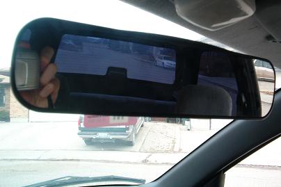
The photo below shows the two places where I had to bend the air dam on each side. The undesirable effect of looking through and seeing the ground is eliminated once the undertray is in place.
__________________

|

|

|
 03-23-2007, 10:17 AM
|
#5
|
|
Registered Member
Join Date: Mar 2007
Posts: 1,138
Country: United States
|
continued...
At this point I had the air dam in its final shape, attached to the vehicle. It might have worked out okay to just mount it to the vehicle and call it done, but I wanted to do a little more to make it more sturdy and more functional. So I added the internal bracing and the undertray. The bracing is made from the same binder strip material as the rest of the dam, and the undertray is made of Coroplast.
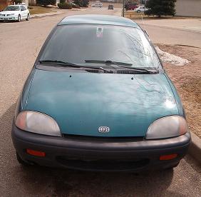
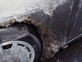
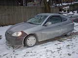
I started on the bracing by making little L-brackets for all of the carriage bolts that were in the binder strip on the lower edge of the dam, and attaching the brackets to the dam. On the ends of the air dam, the bracing goes from the inner front of the dam to the inner rear part that faces the wheel well. This helps give some strength to the rear part, which is otherwise not secured to anything and would likely flutter some due to air currents in the wheel well. In the center of the air dam, the bracing goes straight back toward the rear of the body, and then is bent in an S so it can be secured to the underside of the vehicle. For the rear mounting point I located a couple of holes that some of the factory undertray parts were attached to, removed the factory push-rivets, and put in carriage bolts. Having this brace go straight back and then make the S-curve gave the undertray a longer surface to attach to and be supported by.
First photo shows the little L-brackets and the carriage bolt in the lower binder strip. Second shows the S-curve and the attachment point. Third shows the flat surface to attach the undertray to, the bracing on the end of the air dam, and my knee. 
__________________

|

|

|
 03-23-2007, 10:19 AM
|
#6
|
|
Registered Member
Join Date: Jan 2007
Posts: 291
Country: United States
|
that actually looks pretty good  . someday i will put some effort into the aesthetics of my aero mods  .
__________________
Best tank= 81.23 mpg on july 1st 2008
SAVE SOME GAS, SAVE THE WORLD!

|

|

|
 03-23-2007, 10:20 AM
|
#7
|
|
Registered Member
Join Date: Mar 2007
Posts: 1,138
Country: United States
|
almost finished...
For the undertray, I first made a pattern by gluing together a few pieces of foam-core board, cutting it to shape, drilling holes through it and the underlying bracing or brackets, and securing it with nylon push-rivets. There was no rain in the forecast, so I used this foam-core undertray for several days before making the final one out of Coroplast. I made some vortex generators (VGs) out of aluminum flashing and glued them to the Coroplast with Gorilla Glue. Of course, the Gorilla Glue foams and squirts out, so I had to sand some places flush after the glue set. The VGs are about an inch tall and are mounted at a 15 degree angle from the centerline of the vehicle. The height and the angle were chosen based on the VG work that the Mitsubishi Evo engineers did. The idea of the vortex generators is to virtually extend the length of the undertray to control airflow under the body for a little farther. The undertray by itself would have controlled the airflow over the front suspension subframe. I am hoping that the VGs will extend this control back a little farther to where the exhaust and fuel tank protrude downward. The efficacy of the VGs is surely small and unproveable, but I like them and they are fun to talk about, so I put them on. HA! Anyway, the trailing edge of the undertray is about as far back as the oil drain plug, and is about 2 inches lower. I think that this amount of space will allow plenty of airflow beneath the engine and don?t expect any cooling problems. Plus, the air dam should actually force some additional air up and into the lower grille opening, again allowing for plenty of cooling. I like the undertray a lot because it is the kind of detail that could be skipped and hardly anyone would have the snap to even ask about it, but people in the know understand that it is a very important part of making a functional air dam versus a cosmetic one.
The photos below show (1) the unmounted undertray, (2) the mounted undertray and the nylon push-rivets, and (3) a view toward the rear of the vehicle showing how the undertray should help deflect a lot of air away from the rough underside.
__________________

|

|

|
 03-23-2007, 10:22 AM
|
#8
|
|
Registered Member
Join Date: Mar 2007
Posts: 1,138
Country: United States
|
conclusion...
Here is the finished product on my dirty Element. I like how it looks, and my 12-year-old son agrees. It is still high enough off the ground to clear MOST curbs. I will need to be careful not to damage it. I might eventually paint it, but I think the color is fine for now.

I do not have any gas mileage data yet to determine whether this was a good fuel efficiency mod or not. For what it’s worth, all of the placebo effects seem to be in place. I am easily able to imagine that my coast-down times are longer and that the vehicle is more stable in crosswinds. Also, something I didn’t expect is that the vehicle seems quieter inside, which is nice. Over time I will be able to collect data, do some analysis, and see if I have really made an improvement or not. And if it really does become a science project for one of my kids (or if I get bored one non-windy weekend), I will do some real A-B-A coast-down tests to see if I can measure a Cd improvement or not.
__________________

|

|

|
 03-23-2007, 10:25 AM
|
#9
|
|
Registered Member
Join Date: Mar 2007
Posts: 1,138
Country: United States
|
Quote:
Originally Posted by jwxr7

that actually looks pretty good  . someday i will put some effort into the aesthetics of my aero mods  . |
Thanks!
__________________

|

|

|
 03-23-2007, 10:29 AM
|
#10
|
|
Registered Member
Join Date: Mar 2006
Posts: 1,225
Country: United States
|
Nice craftmanship. How is the Belly tray attached? Can you remove the Airdam and still have the Belly tray? Just something else you can test for FE, with and without airdam. Do you notice any quicker warmup times?
Nice Job.
__________________
|

|

|
 |
|
 Posting Rules
|
You may not post new threads
You may not post replies
You may not post attachments
You may not edit your posts
HTML code is Off
|
|
|
|
 » Car Talk & Chit Chat
 |
|
|
|
|
|
|
|
|
|
|
 » Fuelly iOS Apps
 |
|
|
 » Fuelly Android Apps
 |
|
|
|
|
|